
Showing posts with label 5. Room Acoustics and Reverberation. Show all posts
Showing posts with label 5. Room Acoustics and Reverberation. Show all posts

5.1 Introduction
Room acoustics/reverberation affects the way a space sounds. A high reverberation time can make a room sound loud and noisy. Speech intelligibility is also a function of reverberation, a high reverberation time causes speech to sound muffled and muddy. Rooms designed for speech therefore have a low reverberation time: ≤1 second.
A high reverberation time can enhance a music hall by adding richness, depth and warmth to music. A higher level of reverberation within a concert hall is therefore critical. Illustration 2 provides indicative reverberation times for a range of building types and room volumes.
The reverberation time of a room is defined as the time it takes for sound to decay by 60 dB after an abrupt termination. The reverberation time of a room is linked to the total quantity of soft treatments and the volume of the room, see below.

Acoustic Properties of Materials
To control reverberation time, acoustic absorption is used. Absorbent materials conventionally take two forms; fibrous materials or open celled foam, 3. Fibrous materials absorb sound, since sound waves force the fibres to bend and this bending of the fibres generates heat. The conversion of acoustic energy into heat energy results in the sound effectively being absorbed. In the case of open celled foam, the air movement resulting from sound waves pushes the air particles through the small narrow passages which in turn generate a viscous loss along with heat.
Architecturally, fibrous materials and open celled foams are not particularly attractive or robust. It is therefore common to cover these materials with an acoustically transparent finish such as a tissue, cloth, slatted wood, perforated materials; wood, metal, plasterboard and so on.
The thickness of a given material along with properties such as its fibrosity governs the acoustic performance of a product. Finishes within a space are therefore defined in terms of their absorption coefficient. This is a number between 0.0 (purely reflective), for example stone, tiles, concrete and 1.0 (100% absorbent), products with this rating include high performance acoustic ceiling tiles, slabs of mineral wool, etc.
Products such as carpets have an absorption coefficient between 0.1 and 0.3 depending on their thickness. Perforated plasterboard generally provides around 0.6 to 0.7. It is also common to classify absorbent materials in categories, A to E, where A is highly absorbent and E is almost fully reflective.

5.2 Performance Standards – BB93, HTM and BREEAM
Performance Requirements
The function of a space governs its acoustics requirements. Spaces which need to be quiet and where speech intelligibility is important require a low reverberation time.
BB93 ‘Acoustics Design for Schools’
Table 1.5 of BB93 provides a comprehensive list of performance requirements for educational spaces. This table is used as a benchmark for many buildings including multifunctional buildings and higher educational facilities.

BREEAM Offices
At present BREEAM Offices does not provide performance requirements with respect to room acoustics, therefore the 1 second reverberation time BB93 requirement for offices is commonly used.
HTM - Health Technical Memorandum Acoustics
HTM states that ‘Sound-absorbent treatment should be provided in all areas (including all corridors), except acoustically unimportant rooms (storerooms etc), where cleaning, infection control, patient-safety, clinical and maintenance requirements allow.
Acoustically-absorbent materials should have a minimum absorption area equivalent to a Class C absorber (as defined in BS EN ISO 11654:1997) covering at least 80% of the area of the floor, in addition to the absorption that may be provided by the building materials normally used. If a Class A or B absorbent material is used, less surface area is needed.
Acoustic absorption is likely to be needed in large open spaces such as atria, particularly in localised areas.
MACH Acoustics advises that an acoustic consultant be appointed to undertake a detailed assessment if an alternative to ceiling tiles is to be used.

The function of a space governs its acoustics requirements. Spaces which need to be quiet and where speech intelligibility is important require a low reverberation time.
BB93 ‘Acoustics Design for Schools’
Table 1.5 of BB93 provides a comprehensive list of performance requirements for educational spaces. This table is used as a benchmark for many buildings including multifunctional buildings and higher educational facilities.

BREEAM Offices
At present BREEAM Offices does not provide performance requirements with respect to room acoustics, therefore the 1 second reverberation time BB93 requirement for offices is commonly used.
HTM - Health Technical Memorandum Acoustics
HTM states that ‘Sound-absorbent treatment should be provided in all areas (including all corridors), except acoustically unimportant rooms (storerooms etc), where cleaning, infection control, patient-safety, clinical and maintenance requirements allow.
Acoustically-absorbent materials should have a minimum absorption area equivalent to a Class C absorber (as defined in BS EN ISO 11654:1997) covering at least 80% of the area of the floor, in addition to the absorption that may be provided by the building materials normally used. If a Class A or B absorbent material is used, less surface area is needed.
Acoustic absorption is likely to be needed in large open spaces such as atria, particularly in localised areas.
MACH Acoustics advises that an acoustic consultant be appointed to undertake a detailed assessment if an alternative to ceiling tiles is to be used.

5.3 Estimating Levels of Room Acoustic Treatments
The key to understanding the required level of room acoustic treatments is to study the relevant equation in section 5.1. To implement this equation, MACH Acoustics provide an excel spreadsheet 1 which can be acquired by email from ze@machacoustics.com. This spreadsheet can be used to find the exact required levels of room acoustic treatments. Estimating levels of room acoustics treatments such to approximate the required level of soft treatment, four factors need to be considered:
1 Required reverberation time
2 The average ceiling height
3 The floor finish
4 Added acoustic treatment (acoustic ceiling tiles, acoustic ceiling panels, acoustic wall panels...)
The tables below 3 to 5 present the amount of total absorption required, as a percentage of the floor area, to control the reverberation time based on the four factors above. The three different tables are provided for hard floor finishes, industrial carpet and an industrial carpet placed on an industrial underlay.

Example 1 - Carpeted Office, Ceiling Height of 2.8m and Required RT of 1 Second
From 4 the required levels of surface treatment are found by multiplying the floor area with the required percentage, for example
28% * 60m2 = 0.28 * 60 = 16.8m
16.8m2 of 100% acoustic absorption is therefore required within this 60m2 space.
Correction for Material Selection
The acoustic absorption of finishes is between 0 and 100% absorption, therefore a scaling factor is also needed for a given finish. As noted, materials are often rated between A and E, the scaled factors for these materials is therefore given below.
A = 1.25 * surface area of finish - see section 5.4
B = 1.42 * surface area of finish - see section 5.5
C = 2.00 * surface area of finish - see section 5.6
Example 1 - Continued
Perforated plasterboard with a Class C rating is proposed for the soffit finish. As such 33.6m2 of perforated plasterboard is required to achieve a reverberation time of 1 second.
More than One Finish
If more than one finish type is being proposed please see BB93, example Option C.
Example 2 BB93 Primary School Classroom
60m2 Classroom with a fl oor to ceiling height of 3.2m.
BB93’s reverberation time target is 0.6s
The floor is carpeted; hence 69% of the floor area is required to be treated.
0.69 * 60 = 41.4m of Treatment is required
Option A - Class A ceiling tiles are proposed to be used, therefore 51.75m2 of treatment is needed. This figure is less that the floor area; hence a plasterboard border could be used.
Option B - Class B suspended rafts are proposed, the required area of the rafts is therefore 58.8m2.
Option C - Class B suspend rafts, in combination with 10m2 of Class A wall panels (10/1.25=8, 41.4-8=33, 33*1.42=46.9), therefore 46.9 m2 of suspend rafts are required.
Option D – The classroom ceiling height is dropped to 2.4m, Class B suspended rafts are proposed, the required area of the rafts is therefore 40m2.

1 Required reverberation time
2 The average ceiling height
3 The floor finish
4 Added acoustic treatment (acoustic ceiling tiles, acoustic ceiling panels, acoustic wall panels...)
The tables below 3 to 5 present the amount of total absorption required, as a percentage of the floor area, to control the reverberation time based on the four factors above. The three different tables are provided for hard floor finishes, industrial carpet and an industrial carpet placed on an industrial underlay.

Example 1 - Carpeted Office, Ceiling Height of 2.8m and Required RT of 1 Second
From 4 the required levels of surface treatment are found by multiplying the floor area with the required percentage, for example
28% * 60m2 = 0.28 * 60 = 16.8m
16.8m2 of 100% acoustic absorption is therefore required within this 60m2 space.
Correction for Material Selection
The acoustic absorption of finishes is between 0 and 100% absorption, therefore a scaling factor is also needed for a given finish. As noted, materials are often rated between A and E, the scaled factors for these materials is therefore given below.
A = 1.25 * surface area of finish - see section 5.4
B = 1.42 * surface area of finish - see section 5.5
C = 2.00 * surface area of finish - see section 5.6
Example 1 - Continued
Perforated plasterboard with a Class C rating is proposed for the soffit finish. As such 33.6m2 of perforated plasterboard is required to achieve a reverberation time of 1 second.
More than One Finish
If more than one finish type is being proposed please see BB93, example Option C.
Example 2 BB93 Primary School Classroom
60m2 Classroom with a fl oor to ceiling height of 3.2m.
BB93’s reverberation time target is 0.6s
The floor is carpeted; hence 69% of the floor area is required to be treated.
0.69 * 60 = 41.4m of Treatment is required
Option A - Class A ceiling tiles are proposed to be used, therefore 51.75m2 of treatment is needed. This figure is less that the floor area; hence a plasterboard border could be used.
Option B - Class B suspended rafts are proposed, the required area of the rafts is therefore 58.8m2.
Option C - Class B suspend rafts, in combination with 10m2 of Class A wall panels (10/1.25=8, 41.4-8=33, 33*1.42=46.9), therefore 46.9 m2 of suspend rafts are required.
Option D – The classroom ceiling height is dropped to 2.4m, Class B suspended rafts are proposed, the required area of the rafts is therefore 40m2.


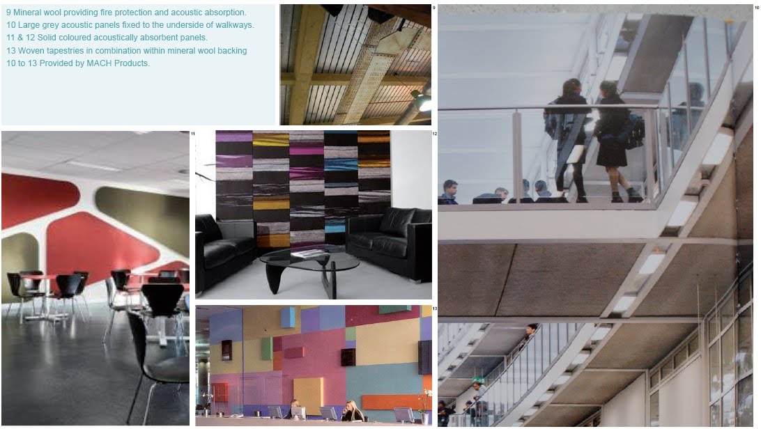


5.7 Sustainable Acoustic Absorption
Acoustic absorption is often based around mineral wool, a product containing huge level of embodied energy along with the negative impact of rock extraction. Alternatively absorption can be provided from sheep’s wool 1, recycled plastic bottles 2, recycled cloth 3, mashed up newspapers 4, wood scraps 5, recycled car dashboards 6, recycled cloth/foam and so on.
Architecturally, sheep’s wool and other green acoustic absorbers need to be fi nished for aesthetic reasons and to enhance robustness. This architectural finish is simply required to be acoustically transparent; such as perforated wood/metal, tissues, cloth, felts and other finishes.
MACH Acoustics has proposed to use a waste product from Tandem Chairs for one of our green projects 8. These chairs are formed from routed plywood sheets such to make the elements making up the Tandem Chair. The waste product is a plywood sheet containing large holes 9. These holes could be slightly reshaped and covered with black tissue.
Illustration 7 shows the use of Bamboo for providing an architectural acoustically transparent finish


Architecturally, sheep’s wool and other green acoustic absorbers need to be fi nished for aesthetic reasons and to enhance robustness. This architectural finish is simply required to be acoustically transparent; such as perforated wood/metal, tissues, cloth, felts and other finishes.
MACH Acoustics has proposed to use a waste product from Tandem Chairs for one of our green projects 8. These chairs are formed from routed plywood sheets such to make the elements making up the Tandem Chair. The waste product is a plywood sheet containing large holes 9. These holes could be slightly reshaped and covered with black tissue.
Illustration 7 shows the use of Bamboo for providing an architectural acoustically transparent finish


5.8 Thermal Insulation and Acoustic Absorption Combined
Thermofleece, Warmcell, Pavatex, Rockwool and other fibrous type materials all provide good levels of thermal insulation, as well as high levels of acoustic absorption. These products are therefore used to enhance the U-values of a building envelope. Fibrous materials can also be used to add acoustic absorption to a room. The acoustic absorption is achieved by installing the thermal, fibrous insulation into the building envelope and
then lining a roof/facade with an acoustically transparent finish for example a perforated or slatted finish. Note that the use of vapour barriers between the lining and the thermal insulation is seen as acceptable, but this is dependent upon the thickness of the vapour barrier.
Put simply, providing the sound within a room can reach the
fibrous, thermal insulation within the roof make-up, the thermal insulation will also provide good levels of acoustic absorption.
Case Study – Eden’s Education Buildings
The roof to Eden’s Educational Building is formed from a timber structure, see illustrations 10 and 11. The warm cell was used to provide the thermal insulation. To achieve the acoustic requirements of the exhibition space the plywood sheet used for lateral bracing was perforated to 20% open area. This principle has been used across a range of schools, higher education buildings and other MACH projects.

then lining a roof/facade with an acoustically transparent finish for example a perforated or slatted finish. Note that the use of vapour barriers between the lining and the thermal insulation is seen as acceptable, but this is dependent upon the thickness of the vapour barrier.
Put simply, providing the sound within a room can reach the
fibrous, thermal insulation within the roof make-up, the thermal insulation will also provide good levels of acoustic absorption.
Case Study – Eden’s Education Buildings
The roof to Eden’s Educational Building is formed from a timber structure, see illustrations 10 and 11. The warm cell was used to provide the thermal insulation. To achieve the acoustic requirements of the exhibition space the plywood sheet used for lateral bracing was perforated to 20% open area. This principle has been used across a range of schools, higher education buildings and other MACH projects.

5.9 Thermal Mass and Acoustic Absorption
Thermal mass cooling is an important consideration in sustainable building design. Conventional acoustic absorbent materials are added to the soffit of a building, this design therefore clashes with thermal mass cooling. There are two solutions to this problem. The first is to apply the acoustic treatment to the walls, this works but can take up a lot of wall area and can be expensive. It is also important to maintain the acoustic treatment well above finger height, in order to increase the durability and control the cost of maintaining the acoustic finishes.
The second method is to suspend the acoustic treatment. Illustration 1 provides a range of design options which provides both acoustical absorption and thermal cooling.
2 - Acoustic beams can be extremely effective since all six sides of the beams will provide acoustic absorption.
3 - Raft ceilings - it is often the case that 30-50% of the ceiling can be covered whilst still providing the thermal cooling. Rafts of acoustic treatment can therefore be used below concrete soffits.
4 - Suspended acoustic panels - A similar design to that of 2, but in this case, the acoustic panels are suspended on wires.
5- Acoustic light fittings - Perforated metal wings are added to the side of a light. Again, this is an effective method of adding acoustic absorption to a space, since both the top and bottom of the panels provide absorption.

The second method is to suspend the acoustic treatment. Illustration 1 provides a range of design options which provides both acoustical absorption and thermal cooling.
2 - Acoustic beams can be extremely effective since all six sides of the beams will provide acoustic absorption.
3 - Raft ceilings - it is often the case that 30-50% of the ceiling can be covered whilst still providing the thermal cooling. Rafts of acoustic treatment can therefore be used below concrete soffits.
4 - Suspended acoustic panels - A similar design to that of 2, but in this case, the acoustic panels are suspended on wires.
5- Acoustic light fittings - Perforated metal wings are added to the side of a light. Again, this is an effective method of adding acoustic absorption to a space, since both the top and bottom of the panels provide absorption.

5.10 Acoustic Beams
Suspended acoustic treatments can be an effective way of reducing the reverberation time within a given space, since these forms of acoustic absorption provide absorption from more than one side/surface. Image 6 is Dartington School, A MACH Acoustics project encompassing acoustic beams produced through MACH
Products. To meet BB93 requirements additional 300mm white ceiling tiles run around the perimeter of these spaces.

Type L1 - 800mm wide foil, 48mm acoustic absorption
Type L2 - 800mm wide foil, 30mm acoustic absorption
Type L3 - 600mm wide foil, 30mm acoustic absorption
Type C1 - 6mm needle-felt carpet tile - 0.15 αW
Type C2 - Carpet tiles with a felt backing - 0.25 αW
Type C3 - Lino as used within science labs - 0.00 αW
Products. To meet BB93 requirements additional 300mm white ceiling tiles run around the perimeter of these spaces.

Type L1 - 800mm wide foil, 48mm acoustic absorption
Type L2 - 800mm wide foil, 30mm acoustic absorption
Type L3 - 600mm wide foil, 30mm acoustic absorption
Type C1 - 6mm needle-felt carpet tile - 0.15 αW
Type C2 - Carpet tiles with a felt backing - 0.25 αW
Type C3 - Lino as used within science labs - 0.00 αW
5.11 Acoustics of Open Plan Offices
Privacy indicates the level of acoustic separation between desks in an open plan offi ce. If privacy levels are too low, speech, phone calls and other noise sources can cause a noise nuisance to multiple office users. Privacy between work stations is the main acoustic consideration in the design of open plan offices.
Privacy is both a function of background noise and the prorogation of sound between work stations. As such it is important to consider the design of environmental noise break in or services noise; both these parameters should not be designed too low. Background noise levels within a naturally ventilated building are hard to keep constant due to variations in road traffic levels, the potentially quiet location of the building and other factors. The use of acoustic screen and other factors within the office space therefore become more critical in these buildings.
BREEAM background noise requirements are a function of office size; large open plan offices have a higher noise requirement. Additionally, an upper and low level is provided by BREEAM such to guarantee a degree of noise masking in large offices.
In MACH Acoustics experience offices can be designed with little or no acoustic absorption whilst still providing a suitable acoustic environment. The key is to ensure that line of sight between desks is obstructed by screens, the layout of the building or other elements. It is also important to prevent reflections from hard surface/soffits. This can be done by placing panels of acoustics absorption over desks in combination with a coffered ceiling or down-stand beams.

Privacy is both a function of background noise and the prorogation of sound between work stations. As such it is important to consider the design of environmental noise break in or services noise; both these parameters should not be designed too low. Background noise levels within a naturally ventilated building are hard to keep constant due to variations in road traffic levels, the potentially quiet location of the building and other factors. The use of acoustic screen and other factors within the office space therefore become more critical in these buildings.
BREEAM background noise requirements are a function of office size; large open plan offices have a higher noise requirement. Additionally, an upper and low level is provided by BREEAM such to guarantee a degree of noise masking in large offices.
In MACH Acoustics experience offices can be designed with little or no acoustic absorption whilst still providing a suitable acoustic environment. The key is to ensure that line of sight between desks is obstructed by screens, the layout of the building or other elements. It is also important to prevent reflections from hard surface/soffits. This can be done by placing panels of acoustics absorption over desks in combination with a coffered ceiling or down-stand beams.

5.12 Creative Room Acoustics - Atrium and Open Plan Office - Bristol University
Brief
Bristol University were concerned about the spread of noise across the various fl oors through a large atrium. Concerns were also raised with respect to a cafe at the base of the Atrium. The question was asked “what can be heard and what can we do to suppress the spread of noise?” The building was proposed to be naturally ventilated with an exposed concrete soffit; further concerns were raised with respect to the spread of noise across the open plan office floors.
Design Scheme
As in the case of most room acoustic assessments, MACH Acoustics used a detailed computer model of the building. This modelling technique enabled the spread of noise from a source or multiple sources to be mapped across an office floor or through a building section. Determining the spread of noise and the effects of soft treatments along with acoustic screening is therefore possible and highly accurate method of modeling.
A set of results from MACH Acoustics work is shown above. The model on the left 3 shows the spread of noise from the cafe to the ground floor office accommodation. Here it can be seen that high levels of noise spread from the atrium to the office accommodation. Based upon the results of audio simulations and auralisation the university required improved levels of separation between these spaces. The right hand image shows the result of adding acoustic panels to the soffit of the office spaces, in close proximity to the atrium. To reduce the spread of noise an acoustic screen was also used. This did not compromise the proposed natural ventilation scheme.
Further audio simulations were presented.

Bristol University were concerned about the spread of noise across the various fl oors through a large atrium. Concerns were also raised with respect to a cafe at the base of the Atrium. The question was asked “what can be heard and what can we do to suppress the spread of noise?” The building was proposed to be naturally ventilated with an exposed concrete soffit; further concerns were raised with respect to the spread of noise across the open plan office floors.
Design Scheme
As in the case of most room acoustic assessments, MACH Acoustics used a detailed computer model of the building. This modelling technique enabled the spread of noise from a source or multiple sources to be mapped across an office floor or through a building section. Determining the spread of noise and the effects of soft treatments along with acoustic screening is therefore possible and highly accurate method of modeling.
A set of results from MACH Acoustics work is shown above. The model on the left 3 shows the spread of noise from the cafe to the ground floor office accommodation. Here it can be seen that high levels of noise spread from the atrium to the office accommodation. Based upon the results of audio simulations and auralisation the university required improved levels of separation between these spaces. The right hand image shows the result of adding acoustic panels to the soffit of the office spaces, in close proximity to the atrium. To reduce the spread of noise an acoustic screen was also used. This did not compromise the proposed natural ventilation scheme.
Further audio simulations were presented.

5.13 Creative Room Acoustics - Foreign and Commonwealth Office FCO
Brief
The FCO proposed to cover one of their four courtyards with a glazed structure. To further enhance this space a new 9 by 9m, 5 storey office block was proposed to be erected in centre of the courtyard.
Having previously covered one of the smaller courtyards, acoustics was seen to be a significant issue.
Design Scheme
One the most important aspects when designing room acoustic finishes is to consider that all one is doing is adding the required level of fibrous or open celled material to a given space. It is therefore possible to be exceptionally creative when undertaking this process.
Allies and Morrison’s proposal was therefore to clad the tower with acoustically absorbent fins 1. Such to assess the feasibility of this proposal, a 3D acoustic model of the spaces was formed 2. This model was used to assess the acoustic design of the fins 3 to 5 as well as the required levels of room acoustics treatments.
The results of the assessment indicated that providing the fins were 250mm deep, 25mm wide and at 750mm centres, the required reverberation time of 1.5 second would be complied with. Aesthetically, the design team considered the fin depth to be too deep. The metal structures supporting the roof were then proposed to also be acoustically clad thus adding more absorption area 6. This reduced the fin depth down to 140mm.

5.14 Creative Room Acoustics - Scarlet Hotel and SPA - Auralisation
This was a challenging project where Spa treatment rooms were proposed to be formed from tents located within the Scarlet Spa Hotel, Cornwall 7. These tents 10 did not contain doors and were to be seen as lightweight structures. Acoustic separation between the tents was therefore addressed in depth. Results were presented in terms of a real time audio simulation 8 & 9.
Design Scheme
The key to this project was to determine the required performance requirements. This was done through MACH Acoustics in-house auralisation tools. This process enabled the end user to hear the building before it was built. The effects of noise masking, sound transfer and background music, were all represented.
Such to provide the client design goals, a detailed computer model was used to assess the spread of sound between tents. This tool was used to assess the effects of room acoustic treatments, curtains, the layout of the Spa and other architectural features.
The result is a fantastic Spa with a very different look and open feel. The tents provide a warm and comfortable environment. The level of acoustic separation between tents achieved the required privacy levels.

Design Scheme
The key to this project was to determine the required performance requirements. This was done through MACH Acoustics in-house auralisation tools. This process enabled the end user to hear the building before it was built. The effects of noise masking, sound transfer and background music, were all represented.
Such to provide the client design goals, a detailed computer model was used to assess the spread of sound between tents. This tool was used to assess the effects of room acoustic treatments, curtains, the layout of the Spa and other architectural features.
The result is a fantastic Spa with a very different look and open feel. The tents provide a warm and comfortable environment. The level of acoustic separation between tents achieved the required privacy levels.

5.15 Creative Room Acoustics - Allies and Morrison Offices
Brief
The brief was to provide room acoustic treatments to acoustically soften the reception spaces at Allies and Morrison’s Offices 1
Design Scheme
The challenge here was to provide design options which fit in with the dramatic, hard, minimalistic reception space. Two design approaches were proposed. The first was to added small amounts of treatment in many locations. These were as follows: to the rear of four large cupboards 2, to the display cabinets 3, to the underside of shelves 4, suspended panels fixed into the lighting track 5.
The alternative proposal was to add larger quantities in fewer locations. This included the end wall 6, here a metal panel with a solid foam infill was proposed, picture 7 shows a sample of this product. The second proposal was to add acoustic beams 9 in front of the window, behind the reception 8.


The brief was to provide room acoustic treatments to acoustically soften the reception spaces at Allies and Morrison’s Offices 1
Design Scheme
The challenge here was to provide design options which fit in with the dramatic, hard, minimalistic reception space. Two design approaches were proposed. The first was to added small amounts of treatment in many locations. These were as follows: to the rear of four large cupboards 2, to the display cabinets 3, to the underside of shelves 4, suspended panels fixed into the lighting track 5.
The alternative proposal was to add larger quantities in fewer locations. This included the end wall 6, here a metal panel with a solid foam infill was proposed, picture 7 shows a sample of this product. The second proposal was to add acoustic beams 9 in front of the window, behind the reception 8.


5.16 Creative Room Acoustics - Kent University 500 Seat Round Auditorium
Brief
As part of a large conference/educational building, Kent University proposed to build a 500 seat Auditorium. The requirement was to provide clear speech, minimising the need for a public address system. One of the main design challenges was fitting this space into a round building.
Design Scheme
The roundness of this building had to be considered carefully. Side wall reflectors placed at the correct angle were used to minimise sound focusing and enhance speech levels at the audience. Additionally, acoustic absorption was placed on the rear walls 12. The design of the ceiling was undertaken using mirror imaging methods, such that the ceiling angles reflected the spoken voice to the rear of the audience minimising the need for a sound reinforcement system.
The overall acoustic performance and the effects of design changes were all assessed by means of a detailed computer model of the space. This is a useful and sophisticated method of enabling design changes to be assessed and ensured that the maximum level of acoustic performance for the auditorium could be met.


Subscribe to:
Posts (Atom)

 Posts

